University at Buffalo (UB)
Instrumentation
The laboratory is equipped with a variety of instrumentation options, which include motion and loading sensors, as well as strain gauges. All instrumentation is calibrated annually and verified before each project. Calibration certificates of all instruments can be provided upon request.
Motion Sensors
String Potentiometers
Our string potentiometers are manufactured from SpaceAge Control and Celesco. They come in different maximum displacement options, to provide a more precise reading and depending on the project needs:
- +/- 2 inches
- +/- 6 inches
- +/- 20 inches
- +/- 25 inches
Data sheets
Linear Potentiometer
As with our string potentiometers, our linear potentiometers come in the following maximum displacement options and manufactured by ETI Systems:
- +/- 0.25 inch
- +/- 0.5 inch
- +/- 1.0 inch
- +/- 2.0 inches
Data sheet
Accelerometers
The lab is also equipped with Honeywell (formally known as Sensotec) accelerometers. These accelerometers, model AG111, have the following performance:
- Ranges: ±10 peak g
- Sensitivity:
- Nominal: 3.8 mV/g
- Range: 2.4-5.0 mV/g
- Usable Frequency Range: 0-400 Hz
- Mounted Resonant Frequency: 1,000 Hz
Data sheet
Loading Sensors
Standard Load Cells
We have multiple load cells with different load capacities. Typically, these load cells are used as a reference when calibrating custom made load cells, but can also be used for non-destructive lab testing. These load cells are sent out annually for calibration and their certificates can be provided upon request. Below is a table of our available standard load cells.
| Capacity | Manufacturer | Model |
| 2 kN (~450 lbs) | Honeywell | 3173 |
| 5 kip (5,000 lbs) | Honeywell | IC48/J275-04 |
| 10 kip (10,000 lbs) | Honeywell | SWO-10k |
| 50 kip (50,000 lbs) | Honeywell | IC48/J345-01 |
| 300 kip (300,000 lbs) | Honeywell | 41 |
Data Sheets
Custom Made Load Cells
Since many of of the test apparatuses are specifically developed for single experiments and usually results in the test specimens being damaged, in-house, custom built, load cells are often used. The geometric layout of a typical load cell is shown in the image below. They are fabricated from a thick wall of cylindrical steel tube. The turned down wall thickness, height, and radius are determined based on the expected maximum stress in the load cells during testing. These load cells are calibrated upon being fabricated and before each testing thereafter. Calibration certificates of these load cells are made each time they are calibrated and available upon request.

Typical Strain Gage Positioning for Multi-directional Load Cells
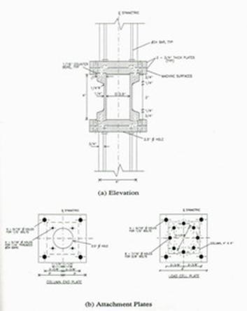
Geometric Layout of a Typical Load Cell
The attachment plates ensure a uniform stress distribution over the entire load cell and provide anchorage into the columns. In the most complicated custom built load cells, axial, shear, and moment stresses can be measured from Wheatstone bridge circuits wired. Simpler compression-tension load cells are also commonly built using only an axial Wheatstone bridge circuit. In addition a majority of the MTS, Miller, and Parker actuators were purchased with a load cell provided by the manufacturer. These load cells are often used in experimentation.
| Load Measuring Device Type | Quantity | Load Capacity | Use |
| 5.5" Five-Component Load Cell 5D-LC-5.5-YEL (axial, x & y shear, x & y moment) | 16 | Axial: 30 [133.6] Shear: 5 [22.3] Moment: 30 [3.39] | Shake Table & Floor Testing |
| 12" Five-Component Load Cell 5D-LC-12-BLU (axial, x & y shear, x & y moment) | 1 | Axial: 100 [454.5] Shear: 20 [89] Moment: 220 [24.86] | Shake Table & Floor Testing |
| 12" Five-Component Load Cell 5D-LC-12-BLK (axial, x & y shear, x & y moment) | 4 | Axial: 100 [454.5] Shear: 20 [89] Moment: 220 [24.86] | Shake Table & Floor Testing |
| Axial (various) (compression:tension) | 10 | 2 - 250 [8.9-1112.06] | Shake Table & Floor Testing |
| Washer (compression only) | 8 | 100 [454.5] | Shake Table & Floor Testing |
| MTS Load Cell | 1 | 2.2 [9.79] | MTS Actuator |
| MTS Load Cell | 2 | 55 [244.65] | MTS Actuator |
| MTS Load Cell | 1 | 110 [489.30] | MTS Actuator |
| MTS Load Cell | 1 | 220 [978.61] | MTS Actuator |
| Lebow Load Cell | 2 | 250 [1112.06] | Miller Actuator |
| Custom Built Load Cell | 4 | 70 [311.38] | Parker Actuator |
| MTS Load Cell Model 661.31E-01 | 3 | 220 [978.61] | MTS Actuator |
| MTS Differential Pressure Cell Model: 660.23 | 5 | 5000 psi [35 MPa] | MTS Actuator |
For information on our 6" Five-Component Load Cell, in-house made, please refer to the below document.
Delta P Cells
Delta P cells are used on many of the actuators available in the laboratory. The MTS servo controllers utilize the Delta P (differential pressure) measured across the actuator piston as a stabilizing variable during the control of an actuator's motion.
Strain
Strain Gauge
While there are several methods of measuring strain, the most common is with a strain gauge, a device whose electrical resistance varies in proportion to the amount of strain in the device. The most widely used gauge is the bonded metallic strain gauge.
The metallic strain gauge consists of a very fine wire or, more commonly, metallic foil arranged in a grid pattern. The grid pattern maximizes the amount of metallic wire or foil subject to strain in the parallel direction (Figure 4). The cross sectional area of the grid is minimized to reduce the effect of shear strain and Poisson Strain. The grid is bonded to a thin backing, called the carrier, which is attached directly to the test specimen. Therefore, the strain experienced by the test specimen is transferred directly to the strain gauge, which responds with a linear change in electrical resistance. Strain gauges are available commercially with nominal resistance values from 30 to 3000 Ω, with 120, 350, and 1000 Ω being the most common values.

Bonded Metallic Strain Gauge
It is very important that the strain gauge be properly mounted onto the test specimen so that the strain is accurately transferred from the test specimen, through the adhesive and strain gauge backing, to the foil itself. A fundamental parameter of the strain gauge is its sensitivity to strain, expressed quantitatively as the gauge factor. The gauge factor is defined as the ratio of fractional change in electrical resistance to the fractional change in length (strain).
The gauge factor for metallic strain gauges is typically around 2. Every strain gauge purchased comes with the exact gauge factor in it's packaging for shunt calibration calculations.