University at Buffalo (UB)
Laboratory Manual
Last updated June 2026
1 Introduction
The Department of Civil, Structural and Environmental Engineering at the University at Buffalo has an extensive earthquake simulation, structural testing and geotechnical engineering testing facility. The facility comprises four distinct spaces, two of which house experimental equipment. These spaces are identified as South high bay and North high bay. Receiving, located side by side within Ketter Hall. In addition to these laboratories, Ketter Hall also houses many of the Civil and Structural Engineering faculty offices and a number of smaller laboratories in structural and geotechnical engineering used for research and instruction. These laboratories are also briefly described herein. Figure 2.1 presents a plan drawing of the laboratory facilities.
2 Description of laboratory facilities

Figure 2.1: Floor plan of laboratory facilities (click to enlarge)
2.1 South high bay

Figure 2.2: South high bay within floor plan of laboratory facilities (click to enlarge)
The south high bay of the Structural Engineering and Earthquake Simulation Laboratory is the smaller of the two main experimental spaces located within the laboratory. Figure 2.2 identifies South high bay within the general plan of the laboratory.
It consists of a large rectangular room approximately 70 ft. (21m) long, 65 ft. (20m) wide, and 30 ft. (9m) tall, enclosing a large strong floor area to which large scale or full-sized specimens and structural assemblages can be attached for quasi-static and dynamic testing. A Number of reaction frames are also available for providing lateral support. The area is accessible through a 20 ft. (6m) wide by 13 ft. (4m) high roll up door, and a 12 ft. (3.7m) wide by 12 ft. high (3.7m) roll up door. Both doors are located at the north end of the laboratory and open into the fabrication and receiving areas, which make for excellent accessibility to the loading bay. The laboratory has an overhead bridge crane which is capable of moving materials and test units to any location within the seismic laboratory. Also available within this laboratory are two bearing testing machines. The Large Bearing Testing Machine has been developed and primarily used for commercial testing of large bearings. The Small Bearing Testing Machine is highly versatile and is capable of applying simultaneous compression or tension, shear and rotation on specimens.
2.1.1 Strong floor
The test floor is a five cell reinforced concrete box girder 40 ft. (12.2m) long, 60 ft. (18.3m) wide, and 8 ft. (2.5m) overall in height. The thickness of the top test floor slab is 18 in. (46 cm). Tie down points consist of (4) 2 ½" holes which are arranged symmetrically in both directions. Each tie down point has an axial load allowable capacity of 250 kips (1112kN). Figure 2.3 presents a view of the strong floor including the layout of the tie down points. The tie down pattern is shown in Figure 2.4.

Figure 2.3: View of strong floor with tie down points (click to enlarge)

Figure 2.4: Bolt pattern of strong floor in South high bay (click to enlarge)
2.1.2 Gantry crane
The southern part of the laboratory, Testing Area 1, has a 15 ton / 33 kip (~150kN) capacity overhead bridge crane which is capable of moving materials and test units to any location within the seismic laboratory. Operation by Staff or Trained Personnel only.

Figure 2.5: 15 T gantry crane (click to enlarge)
2.1.3 Shake table S
Also located in Testing Area 1, there is a single degree of freedom shake table. Built by laboratory personnel and students, the table is 4.5 ft. by 4.5 ft. (1.4 m by 1.4 m). The dynamic stroke of the actuator is 6in (i.e., xm = 3 in (762 mm)) and the static stroke is 7.2 in (1,524 mm). The table is driven by a 5.5 kip (24.47 kN) actuator with a MTS 252.25 (MOOG model number 760F264A) servo valve with a rated flow of 15gpm (56.78 lpm).

Figure 2.6: Shake table S in Testing Area 1 (click to enlarge)
2.1.4 Bearing Machines
The laboratory is equipped with two bearing testing machines. The Large Bearing Testing Machine has been developed and primarily used for commercial testing of large bearings. It is capable of applying 1600 kips (7117 kN) vertical load, and lateral displacement of ±5 in. (125 mm) amplitude and 10 in/sec (255 mm/sec) peak velocity. Figure 2.7 and Figure 2.8 present views of the bearing testing machine in the testing of a single elastomeric bearing and of a pair of elastomeric bearings.

Figure 2.7: Testing of a single elastomeric bearing in the large bearing testing machine (click to enlarge)

Figure 2.8: Testing of a pair of elastomeric bearings in the large bearing testing machine (click to enlarge)
The Small Bearing Testing Machine is a highly versatile machine that is capable of applying simultaneous compression or tension, shear and rotation on specimens. It has a 50 kip (223 kN) vertical load capacity (but expandable if a higher capacity load cell is used), ±6 in. (150 mm) horizontal displacement capacity, ±2 degrees rotational capacity and peak speed of over 20 in./sec (0.5 m/sec). Figure 2.9 presents a view of the machine in the testing of an XY-FPS bearing in combined tension and high speed shear.

Figure 2.9: Testing of a bearing in the small bearing testing machine (click to enlarge)
2.1.5 Wind Tunnel
The multi-fan wind tunnel is controlled by a 64 inertia array (8x8) of small axial fans. These fans can be controlled individually or in groups using the supplied software. Each individual fan can reach a maximum of 5,500rpm (rotations per minute). With the damping section installed, wind speeds can reach up to 40mph (~50mph without the damping section). Fully assembled, the tunnel as a length of 10 meters.
It's compromised of multiple segments. These segments can be picked up and re-arranged. Each segment has a width of 1 meter and height of 1.2 meters (the length of each varies). Located on the horizontal sides of the two test segments are either one or two doors that can be opened up to allow access to the wind tunnel. On the segment with two doors are small circular openings to allow test specimens to attach to external fixtures. Additionally, on the segment with one door is a turn table with a diameter of 0.7 meters.
Located right after the multi-fan cone is a honeycomb output with a vibration isolation section. Directly following the vibration isolation is a damping section for flow field quality. This section can be removed.

Figure 2.10 Overal picture of the wind tunnel
2.1.6 Furnace
The electric furnace has a maximum operating temperature of 1,000°C (1,800 °F) and is designed to accommodate a fast ramp-up heating rate. The fire chamber is 1.5 m x 1.5 x 1.5 m (5 ft x 5ft x 5ft). Three high strength refractories are placed at the bottom center, middle left, and middle right sides of the chamber to support loaded elements. The furnace roof is removable and includes a central closure hole to allow placement and force loading of vertically oriented element. The closure hole on one side allows for placement and loading of a horizontally oriented element.

Figure 2.11 Electric furnace with three high strength refractories
2.1.7 Equipment
The South high bay of the laboratories is supplied with (2) MTS Hydraulic Power Supplies. Each of the pumps, 506.81 model, consists of (2) discrete hydraulic pumps with individual flow rates of 70 gpm, for a total of 280 gpm. The pumps can be operated individually or in any combination to achieve the required flow rate. The hydraulic supply, manifolds, is available at several stations throughout the laboratory. Also available are six static actuators (four Parker and two Miller) and eight MTS dynamic actuators.
2.2 North high bay

Figure 2.12: North high bay within plan of laboratory facilities (click to enlarge)
2.2.1 Shake Tables East and West
A set of two high-performance, six degreesn of freedom shake tables, which can be rapidly repositioned from directly adjacent to one another to positions up to 100 feet apart (center-to-center). Together, the tables can host specimens of up to 100 metric tons and as long as 120 feet, and subject them to fully in-phase or totally uncorrelated dynamic excitations.

Figure 2.13: View of shake table west (click to enlarge)
2.2.2 Reaction walls
There are two reaction walls in North high bay, one next to strong floor and one next to the shake table trench.
The physical dimensions of the reaction wall next to strong floor are:
- Length: 41'-0''
- Height: 30'-0''
- Thickness: 2'-0''

Figure 2.14: Reaction wall next to the strong floor (click to enlarge)
The physical dimensions of the reaction wall next to the shake table trench are:
- Length: 23'-0''
- Height: 30'-0''
- Thickness: 2'-0"

Figure 2.15: Reaction wall next to shake table trench (click to enlarge)
2.2.3 Strong floor
The physical dimensions of the strong floor in the north high bay are:
- Lengh: 79'-0"
- Width: 39'-0"

Figure 2.16: North high bay (click to enlarge)
2.2.4 Gantry crane
The north high bay is equipped with a 40 ton and a 20 ton gantry cranes that span width of the testing area and are operated by separate remote controls. Operation is restricted to staff or approved and trained personnel only!

Figure 2.17: 40 ton gantry crane in the north high bay (click to enlarge)

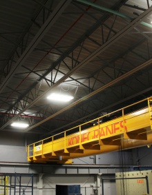
Figure 2.18: 20 ton gantry crane in the north high bay (click to enlarge)
2.2.5 Visitors' gallery
An observation deck is located on the 3rd level of the lab for guests and visitors.

Figure 2.19: Visitor's gallery in the north high bay (click to enlarge)
2.2.6 Control room
Located on the western side of the second floor north bay is an elevated control room. It houses workstations capable of controlling any data acquisition or control system in the lab's north bay. These workstations are preloaded with all the necessary software to run any system in the lab. Additionally, software to quickly visualize and analyze captured data is preinstalled as well.

Figure 2.20: Control room (click to enlarge)
2.2.7 Workshop
A workshop is located on the east side of the 2nd floor in north high bay.
2.2.8 Equipment
The pump room, located in the basement of the north high bay, houses four MTS 506.92 Hydraulic Power Supply (HPS) units, each rated at 185 gpm (700 lpm) flow with 3,000 psi (207 bar) working pressure.
Four hydraulic outlet stations are located along the table trench for connection of hoses. Two stations are used to connect to the moveable tables at any one time and any free stations can be used to allow connection of structural actuators to the strong floor along the north side of the floor for certain configurations.
At the strong floor surface, adjacent to the strong wall, four high flow manual distribution manifolds are located, with four sets of 2 inch hand and check valves to allow connection to the three moveable hydraulic service manifolds. These high flow (800 gpm) hydraulic service manifolds, with additional accumulation, are typically located near the lab reaction walls to provide full flow capacity to the high speed structural actuators. This arrangement will supply the highest available volume flow to the structural actuators for their demanding applications for real time hybrid and other high-demand testing. Also available, are three low flow distribution manifolds along the south edge of the floor that are evenly spaced and each is provided with two sets of hand and check valves on the testing floor level.
2.3 Low bay
2.3.1 Fabrication area
The fabrication area is located between the south and north high bays. The area is approximately 58 ft. (17.7 m) long and 31 ft. (9.5 m) wide, and has direct access to the delivery area and loading bay. Moreover, the area features an additional enclosed 19 ft. by 22 ft. (5.8 m by 6.7 m) restricted machine area and a 12 ft. by 20 ft. (3.7 m by 6.1 m) technician’s office. The area has a 15 kip (66 kN) capacity overhead bridge crane that is capable of moving materials and test units within the fabrication area. A 6 kip (27 kN) capacity forklift is available and typically stored in the fabrication or delivery areas.
A Tinius Olsen universal testing machine is located within the fabrication area. A MTS 150 kip (667 kN) compression/tension machine is located in this area as well. These machines are used in the testing of concrete specimens, in the calibration of load cells, and in the compression testing of elastomeric and sliding bearings.

Figure 2.21: Fabrication area within plan of laboratory facilities (click to enlarge)
2.3.2 Machine shop areas

Figure 2.22: Machine shop area within the plan of laboratory facilities (click to enlarge)
The laboratory maintains facilities and personnel for performing machining, fabrication, welding and assembly of structural systems. The equipment necessary to do so is located and stored within the fabrication area. Available equipment includes the following:
- Large drill press
- Small drill press
- Lathe machine
- Small lathe machine
- Vertical saw
- Horizontal saw
- Surface grinder
- Bench grinder
- Mill machine
- MIG welder
- Tack welder
- Stick welder
- Pipe threading machine
- Inspection table

Figure 2.23: View of machine shop (click to enlarge)
2.3.3 Welding facility
SEESL is equipped with several welding stations that can be moved to anywhere within the lab. The welding machines available are:
- MIG welder
- Tack welder
- Stick welder

Figure 2.24: Welding station (click to enlarge)
2.3.4 Materials storage
In between the south and north bays is a materials storage area. This section of the lab provides a storage place for small concrete specimens where they will also later be tested using concrete compression machines. This area can also be used for preparation work for foundation assembly and pouring. These are then moved to either of the bays for further assembly and testing. Located directly west of this area is a loading bay door for easy delivery of materials and concrete mixing and pouring.

Figure 2.25: Material storage (click to enlarge)
2.3.5 Gantry crane
The machine shop area has a 7.5 T (75 kN) capacity overhead bridge crane that is capable of moving materials and test units within the area.

Figure 2.26: Fabrication area and gantry crane (click to enlarge)
2.3.6 delivery and short-term storage

Figure 2.27: Delivery areas within plan of laboratory facilities (click to enlarge)
There are two delivery areas located in the lab. The first is located between the north high bay and the fabrication area. It is approximately, 14 ft. (4.2 m) tall and 15 ft. (4.5 m) wide and has direct access to the 15 kip (66 kN) capacity overhead bridge crane.
The second is located in the north high bay, on the west side of the lab. This area is approximately 14.5 ft. (4.4 m) tall 15 ft. (4.5 m) wide and has access to two overhead bridge cranes (one being 40 T and the other 20 T).

Figure 2.28: View of a delivery area (click to enlarge)
2.3.7 Rigging equipment
The rigging equipment available is as follows:
- 8 kip (35kN, 8,000 lbs) capacity forklift
- 2 ton strong bac
- 0.45 ton (1,000 lbs) capacity crane basket

Figure 2.29: Forklift (click to enlarge)

Figure 2.30: Strong bac (click to enlarge)

Figure 2.31: Crane basket (click to enlarge)
2.3.8 Personnel platforms
Two electric scissor lifts and a cherry picker are available for lifting personnel within all lab areas.

Figure 2.32: Electric scissor lifts (click to enlarge)

Figure 2.33: Cherry picker (click to enlarge)
2.3.9 Wood fabrication area
The wood fabrication area is equipped with the following:
- Table saw
- Panel saw
- Circular saw
- Air extractor

Figure 2.34 Wood fabrication area (click to enlarge)
3 Laboratory Equipment
3.1 Shake Tables
Key elements of the SEESL are the two movable, six degrees of freedom, shake tables, which can be repositioned from directly adjacent to one another to positions up to 100 feet apart. Together, these tables can host specimens of up to 100 metric tons and as long as 120 feet, and subject them to fully in-phase or totally uncorrelated dynamic excitations. For more information, please refer to this page http://www.buffalo.edu/seesl/services/shake_tables.html

Figure 3.1: Shake table west with instrumentation frame and specimen (w/o table extension)

Figure 3.2: Shake table east (without the table extension)
3.2 Table Extensions
There are the two 7 x 7 meter shake table extension platforms available for each of the shake tables. The Platforms are of welded steel construction with a weight of approximately 9.8 tons. The extensions have painted top surface.

Figure 3.3: View of both shake tables with extension platforms in place (click to enlarge)

Figure 3.4: Shake table East with extension platform (click to enlarge)
3.3 Reaction Walls
Reaction walls and strong floors allow for testing of structural components such as steel trusses and concrete slabs. For further information about the physical data, refer to the referenced pages.

Figure 3.5: Reaction wall next to shake table trench (click to enlarge)

Figure 3.6: Reaction wall next to strong floor (click to enlarge)

Figure 3.7: Plan view of Reaction Walls (click to enlarge)

Figure 3.8: Cross-section of reaction walls (click to enlarge)
3.4 Strong Floors
3.4.1 Strong Floor - South high bay
3.4.1.1 Physical Data
The test floor is a five cell reinforced concrete box girder 40 ft. (12.2 m) long, 60 ft. (18.3 m) wide, and 8 ft. (2.5 m) overall in height. The thickness of the top test floor slab is 18 in. (46 cm). Tie down points consist of (4) 2 ½" holes which are arranged symmetrically in both directions.
3.4.1.2 Capacity Data
Each tie down point has an axial load allowable capacity of 250 kips (1,112 kN).
3.4.2 Strong Floor - North high bay
3.4.2.1 Physical Data
The test floor is a reinforced concrete box girder 79 ft. (24m) long, 39 ft. (11.8 m) wide. The thickness of the top test floor slab is 24 in. (60 cm).
3.4.2.2 Capacity Data
For capacity data of the strong floor in North high bay, please refer to the following page: http://www.buffalo.edu/seesl/services/strong_floors.html
3.4.2.3 Drawings

Figure 3.9: Cross-section view of strong floor in the north high bay (click to enlarge)

Figure 3.10: Cross-section view of strong floor in the north high bay (click to enlarge)
3.5 Hydraulic Power Supply Systems
3.5.1 Hydraulic Power Supply - South high bay
| Device Type | Quantity | Flow Rate (per unit) gpm [lpm] |
| MTS506.81 HPS | 2 | 140* [1,245.5] |
* Flow rate available in increments of 70 gpm (265 lpm)
3.5.2 Hydraulic Power Supply - North high bay
The pump room, located in the basement of the Ketter Hall lab addition, houses four MTS 506.92 Hydraulic Power Supply (HPS) units, each rated at 185 gpm (700 lpm) flow with 3,000 psi (207 bar) working pressure. Each HPS consists of two high pressure, variable volume main pumps and a low pressure “supercharge” pump that draws oil from the reservoir and supplies a constant oil pressure and flow to the inlets of the main pumps. These units have oversized reservoirs to accommodate the additional accumulator oil volume required for high performance dynamic testing. Hydraulic system oil is cooled by pumping hydraulic fluid through a system of heat exchangers (one located on each HPS) that are connected to the campus chilled water system. The chilled water is supplied at an average year-round temperature of 50° F. Temperature-sensitive flow control valves are provided by MTS as part of the HPS assembly. These valves regulate the flow of chilled water through the heat exchangers as a function of hydraulic fluid system temperature. The hydraulic fluid is maintained at an optimum working temperature of 100 – 110° F.

Figure 3.11: MTS 506.92 Hydraulic Power Supply (click to enlarge)
3.5.2.1 Pumps
The laboratory hydraulic distribution system is an integrated solution for the combined functions of seismic and structural testing. The system was designed to minimize system expenditure (by reducing the use of duplication) and to maximize performance and capabilities.
The pump room piping segment is connected to the outputs of the four HPS units and runs directly to the through an opening in the table trench wall. The diameter of the common piping in the HPS room area is 130 mm pressure and 220 mm return line with 2 inch drain lines. The reservoirs of the HPS units are connected together with large diameter piping to provide a common reservoir from which all 8 pumps on the 4 HPS units can draw oil.
The seismic piping system runs along the length of the shake table trench. This piping is sized to allow both the seismic table and structural actuators to run simultaneously for hybrid testing applications with table-mounted specimens coupled with the strong wall at the east end of the trench. Hydraulic outlets with manual valves are located along the trench for positioning of the movable tables, offering maximum flexibility. Outlets are also located along the strong wall for connecting the Hydraulic Service Manifolds for the high flow structural actuators. Flexible hoses are used to connect the table system and the structural actuators to the main hard line distribution outlets.
Four hydraulic outlet stations are located along the table trench for connection of hoses. Two stations are used to connect to the moveable tables at any one time and any free stations can be used to allow connection of structural actuators to the strong floor along the north side of the floor for certain configurations. By design, one trench distribution manifold station will allow one table to be positioned to any one of four locations without breaking hose connections. This helps simplify repositioning of the table system.
The main branch line running from the HPS piping manifold in the table trench area to the east end of the trench is sized to provide in excess of 1200 GPM pressure and 1600 GPM return (average) of oil flow using 150 mm pressure piping and 220 mm return piping with 2 inch drain lines. Wall openings are cast into the concrete structure of the basement and the table trench, through which the hard line is routed.
Over 700 gallons of oil volume accumulation (Figure 3.12) is provided through four distributed accumulation bank systems. These accumulators are located in the basement below the strong floor adjacent to the high flow hydraulic distribution manifolds (see Figure 3.13). These are engineered to operate in a horizontal manner to provide maximum accessibility for maintenance in the basement.

Figure 3.12: MTS Accumulator System (Qty. 4) (click to enlarge)

Figure 3.13: Hydraulic distribution system (click to enlarge)
At the end run of the main branch line, a secondary piping distribution runs south below the strong floor along the strong wall to service the structural testing area. This secondary branch line for structural testing also consists of 150 mm pressure piping and 220 mm return line piping with 2 inch drain lines along the length of the strong wall. Line accumulation from the individual hydraulic service manifolds and the basement accumulation banks supplements the flow above the 800 GPM output from the HPS units as needed. Vertical risers run from the basement level through the strong floor to the four distribution manifolds mentioned earlier. The pressure risers are 130 mm and the return risers 140 mm in diameter. Strong floor cut outs (precast in the floor) allow the passage of the piping system from the basement to the top of the strong floor.
At the strong floor surface, adjacent to the strong wall, four high flow manual distribution manifolds are located, with four sets of 2 inch hand and check valves to allow connection to the three moveable Hydraulic Service Manifolds. This arrangement will supply the highest available volume flow to the structural actuators for their demanding applications for real time hybrid and other high demand testing. These high flow manual distribution manifolds can also be used for general purpose distribution manifolds to connect other actuators for more traditional structural testing applications (when the high flow structural actuators are not in use) adding setup flexibility along the strong wall area.

Figure 3.14: MTS High flow hydraulic distribution manifold (click to enlarge)
Beginning at the fourth high flow structural testing distribution manifold location, approximately 60 feet of 75 mm diameter piping runs below the strong floor along the south edge of the floor. Three low flow distribution manifolds are evenly spaced along this piping run and each is provided with two sets of hand and check valves on the testing floor level. The vertical risers consist of 2 inch SST piping (pressure and return) to each distribution manifold.

Figure 3.15: MTS low flow hydraulic distribution manifold (click to enlarge)
When considered as a single system, the hard line runs and outlet stations in the table trench, and the hard line runs and manifolds along the strong wall and south strong floor allow hydraulic power to be distributed to three sides of the strong floor area. This distribution scheme allows hydraulic power coverage over the majority of the strong floor area.
3.5.2.2 Service Manifolds (Ports)
Three high flow (800 gpm) hydraulic service manifolds with additional accumulation are typically located near the lab reaction wall to provide full flow capacity to the high speed structural actuators. For structural testing applications, these Hydraulic Service Manifolds are used for on/off control with 40 gallons each of pressure and return accumulator banks. These service manifolds each support a single actuator assembly with an 800 gpm servo valve. These hydraulic service manifolds can be positioned throughout the testing laboratory, with high speed testing typically performed at the lab reaction wall where the distribution piping and accumulator systems will maximize the flow capabilities. They can also be positioned at any free station located at the seismic table trench area if needed.

Figure 3.16: MTS 800 GPM hydraulic service manifold (click to enlarge)
Each table system has a dedicated integral hydraulic service manifold with 30 gallons each of pressure and return accumulators.
Two (2) 50gpm hydraulic service manifold are available for connecting the static actuators. Typically, these manifolds are connected to the south strong floor distribution manifolds; however they can be used throughout the laboratory wherever a connection point exists.

Figure 3.17: MTS 293.12 50 GPM hydraulic service manifold (click to enlarge)
3.5.2.3 Flow Rate Data of HPS
| Device Type | Quantity | Flow Rate (per unit) gpm [lpm] |
| MTS Manifold 290 Series | 3 | 50 [189] |
| MTS Manifold 290 Series | 2 | 100 [378.54] |
| MTS Manifold 290 Series | 1 | 250 [946.35] |
3.5.2.4 Oil Filtration and Cleanliness
The hydraulic distribution system is designed to meet an oil filtration quality of ISO 13/10. This level of cleanliness is critical for high fidelity servo valve systems. The system is designed to use Mobil DTE 25 hydraulic fluid or the equivalent. Oil samples are taken at 3 month intervals and sent to MTS for evaluation. If particle counts exceed the ISO 13/10 specification, corrective action is immediately taken. This typically involves flushing the hydraulic distribution system at high flow rates for several hours or days, after which oil samples are again drawn for evaluation.
3.6 Loading Systems
3.6.1 Hydraulic actuators
The laboratories feature numerous actuators suitable for a variety of different testing procedures. For more detailed information regarding our actuators and servovalves, please refer to this page: http://www.buffalo.edu/seesl/services/actuators.html
- MTS Systems Corporation servo-controlled static rated actuator (x2) with a load capacity of 440 kips (1962 kN) and an available stroke of 40 in. The actuator's servovalve has a flow rate of 15 gpm (56.78 lpm), and the actuator has a maximum velocity of 0.393 in./sec (9.982 mm/sec) with that particular valve.
- Miller servo-controlled static rated actuators (x2) with a load capacity of 250 kips (1112.06 kN) and an available stroke of 8 in. (203.2 mm). The actuator's servovalve has a flow rate of 15 gpm (56.78 lpm), and the actuator has a maximum velocity of 0.65 in./sec (16.5 mm/sec) with that particular valve. Force is measured using manufacture supplied load cells and displacement is measured using internally mounted LVDTs.
- MTS Systems Corporation servo-controlled dynamic rated actuator (x3) with a load capacity of 220 kips (978.61 kN) and an available stroke of 40 in.. The actuator's servovalve has a flow rate of 15 gpm (56.78 lpm), and the actuator has a maximum velocity of 0.75 in./sec (19.1 mm/sec) with that particular valve. This particular actuator is equipped with an alternate servovalve for high speed testing which has a flow rate of 800 gpm (3000 lpm), and the actuator has a maximum velocity of 42in./sec (1066.8 mm/sec). Force is measured using a manufacture supplied load cell and displacement is measured using internally mounted LVDTs.
- MTS Systems Corporation servo-controlled dynamic rated actuator (x1) with a load capacity of 220 kips (978.61 kN) and an available stroke of 10 in. (254.0 mm). The actuator's servovalve has a flow rate of 15 gpm (56.78 lpm), and the actuator has a maximum velocity of 0.75 in./sec (19.1 mm/sec) with that particular valve. This particular actuator is equipped with an alternate servovalve for high speed testing which has a flow rate of 250 gpm (946.35 lpm), and the actuator has a maximum velocity of 12.5 in./sec (317.5 mm/sec). Force is measured using a manufacture supplied load cell and displacement is measured using internally mounted LVDTs.
- MTS Systems Corporation servo-controlled dynamic rated actuator (x1) with a load capacity of 110 kips (489.30 kN) and an available stroke of 10 in. (254.0 mm). The actuator's servovalve has a flow rate of 15 gpm (56.78 lpm), and the actuator has a maximum velocity of 1.5 in./sec (38.1 mm/sec) with that particular valve. This particular actuator is equipped with an alternate servovalve for high speed testing which has a flow rate of 250 gpm (946.35 lpm), and the actuator has a maximum velocity of 25 in./sec (635.0 mm/sec). Force is measured using a manufacture supplied load cell and displacements is determined using internally mounted LVDTs.
- Parker servo-controlled static rated actuators (x4) with a load capacity of 70 kips (311.38 kN) and an available stroke of 4 in. (101.60 mm). The actuator's servovalves have flow rates of 15 gpm (56.78 lpm), and the actuators have a maximum velocity of 2.4 in./sec (60.96 mm/sec) with that particular valve. Due to the fact that the actuators are single-ended, they are primarily used for vertical load application. Force is measured using in-house custom built load cells and displacement is measured using external displacement transducers.
- MTS Systems Corporation servo-controlled dynamic rated actuator (x1) with a load capacity of 55 kips (244.65 kN) and an available stroke of 12 in. (304.8 mm). The actuator's servovalve has a flow rate of 90 gpm (340.69 lpm), and the actuator has a maximum velocity of 17 in./sec (431.8 mm/sec) with that particular valve. Force is measured using a manufacture supplied load cell and displacement is measured using internally mounted LVDTs.
- MTS Systems Corporation servo-controlled dynamic rated actuator (x1) with a load capacity of 55 kips (244.65 kN) and an available stroke of 24 in. (609.6 mm). The actuator's servovalve has a flow rate of 15 gpm (56.78 lpm), and the actuator has a maximum velocity of 2.95 in./sec (74.9 mm/sec) with that particular valve. Force is measured using a manufacture supplied load cell and displacement is measured using internally mounted LVDTs.
- MTS Systems Corporation servo-controlled dynamic rated actuator (x1) with a load capacity of 22 kips (97.86 kN) and an available stroke of 6 in. (152.4 mm). The actuator's servovalve has a flow rate of 10 gpm (37.85 lpm), and the actuator has a maximum velocity of 5 in./sec (127.0 mm/sec) with that particular valve. Force is measured using an in-house custom built load cell and displacement is measured using internally mounted LVDTs.
- MTS Systems Corporation servo-controlled dynamic rated actuators (x2) with load capacities of 5.5 kips (24.47 kN) and an available stroke of 6 in. (152.4 mm). One actuators servovalve has a flow rate of 30 gpm (113.56 lpm), and the actuator has a maximum velocity of 50 in./sec (1270.0 mm/sec) with that particular valve. The other actuators servovalve has a flow rate of 15 gpm (56.78 lpm), and the actuator has a maximum velocity of 27 in./sec (685.8 mm/sec) with that particular valve. Force is measured using in-house custom built load cells and displacement is measured using internally mounted LVDTs.
- MTS Systems Corporation servo-controlled dynamic rated actuator (x1) with a load capacity of 2.2 kips (9.79 kN) and an available stroke of 4 in. (101.6 mm). The actuators servovalve has a flow rate of 10 gpm (37.85 lpm), and the actuator has a maximum velocity of 49 in./sec (1244.6 mm/sec) with that particular valve. Force is measured using a manufacture supplied load cell and displacement is measured using internally mounted LVDTs.

Figure 3.18: MTS 243.90T static actuators (click to enlarge)

Figure 3.19: MTS 244.51S dynamic actuator (click to enlarge)
3.6.1.1 Servo-Controllers
| Servo Controller Manufacturer | Quantity (# Channels Controlled) | Control Modes | Servovalve Type(s) Controlled |
| MTS 469D | 1(5) | Acceleration / Velocity / Displacement | 256.80S |
| MTS 407 | 2 | Force / Displacement / Stress | MTS 252.24, 252.25, 256.09, 256.25 |
| MTS FlexTest | 1(6) | Acceleration / Force / Displacement | MTS 252.24, 252.25, 256.09, 256.25 |
3.6.1.2 Hydraulic Service Manifolds
A hydraulic service manifold (HSM) is a hydraulic pressure and flow regulation device that controls pressure to a single test station from the main hydraulic power unit (HPU).
| Device Type | Quantity | Flow Rate (per unit) gpm [lpm] |
| MTS 506.81 HPS | 2 | 140* [1,245.5] |
| MTS Manifold 290 Series | 3 | 50 [189] |
| MTS Manifold 290 Series | 2 | 100 [378.54] |
| MTS Manifold 290 Series | 1 | 250 [946.35] |
| MTS Model 506.92 HPS | 4 | 180** [680] |
| MTS High Flow Hydraulic Distribution manifolds | 4 | 800 |
| Custom Hydraulic Service manifolds | 3 | 800 |
| MTS 293.12 Low Flow Hydraulic Service Manifold | 2 | 50 [189] |
* Flow rate available in increments of 70 gpm (265 lpm)
** Flow rate available in increments of 90 gpm (340 lpm)
3.6.1.3 Integration Options - Actuators, Controllers, Manifolds
It is important to understand that the laboratory is not restricted to the specifications of each particular hydraulic actuator. In an actual experiment a hydraulic actuator system is composed of three major components including the hydraulic cylinder, servovalve, and servo-controller. Due to the fact that the majority of the equipment used in the laboratories is manufactured by MTS Systems, the components of each actuator can be interchanged. Different servovalves can be used on the same hydraulic cylinder to produce low and high speed velocities. This in turn may change the rating of the hydraulic actuator from static to dynamic and vice versa.
Moreover, different servo-controllers may be used depending on the desired experimental set up. For example, an experiment may entail applying a force to a horizontal beam and at the same time ensuring that the beam is kept horizontal. This would require an initial actuator to apply force to the system as well as a second actuator to ensure that the position of the beam is correct. Different servo-controllers can be used that will allow the system to obtain actual feedback from the two actuators so that any necessary corrections can be made immediately.
3.6.2 Testing Machines
3.6.2.1 MTS Axial-Torsion Machine
This machine is capable of biaxial testing of specimens and components of many sizes, up to 4 ft. (1.22 m) in length. Control modes available are force, strain and displacement in axial mode, and torque (in/lb.), strain and rotation (degrees) in torsion mode. The machine has calibrated ranges of 100, 50, 20, and 10 kips, and ± 5, 2.5, 1, and 0.5 in. axially, as well as 50000, 25000, 10000, and 5000 pounds-inch, and 50, 25, 10, and 5 degrees in the torsion mode.

Figure 3.20: MTS Axial-Torsion machine (click to enlarge)
3.6.2.2 Generic Large Bearing Testing Machine
This machine has been developed for the testing of sliding bearings. It is capable of 1600 (7117.2 kN) kips compression (expandable to 2200 kips / 9786.1 kN), lateral load of up to 220 kips (978.6 kN), stroke of ± 5 in. (12.7 cm) and velocities of up to 10 in./sec (254 mm/sec). Bearing plan dimensions can be up to 45 in. (114.3 cm) by 45 in. (114.3 cm). It can be used for the seismic testing of sliding bearings and the characterization of frictional properties of large-dimension material interfaces. The machine can also be used for the testing of elastomeric bearings. The machine is capable of testing pairs of bearings, or a single bearing with the use of rolling cylinders. Figure 3.21 presents a view of this testing machine.

Figure 3.21: Large Bearing testing machine (click to enlarge)
3.6.2.3 Generic Small Bearing Testing Machine
This machine has been developed for the testing of single bearings under controlled conditions of vertical load, lateral movement and rotational movement. It has a 140 kip (622.8kN) vertical load capacity, 55 kip (244.7 kN) horizontal load capacity, ± 6 in. (15.24 cm) horizontal movement capacity with up to 15 in./sec (381 mm/sec) velocity, and rotational capability of ± 2 degrees. Reaction forces can be directly measured by a multi-component load cell which currently has a rated capacity of 20 kips (89 kN) shear and 50 kips (222.4 kN) axial load. The machine can been used in the testing of elastomeric and sliding bearings, including tests under variable axial load and tests of bearings pre-stressed by tendons to prevent uplift. Figure 3.22 presents a view of the testing machine during testing of an elastomeric bearing.

Figure 3.22: Small Bearing testing machine (click to enlarge)
3.6.2.4 Tinius Olsen Universal Testing Machine - 300 kips (1,350 kN)
This machine has been used primarily for testing concrete cylinders, structural steel members, and standard steel test specimens. The machine consists of a dual crosshead, mechanical screw load frame, with a test surface platen having an effective area of 31 in. (79 cm) x 43 in. (109 cm). The platen is 45 in. (114.3) from the lab floor. The crossheads can be placed at any height along the screws to allow testing of specimens up to 72 in. (183 cm) long in tension. The upper crosshead is locked in place during testing, while the lower crosshead moves along the machine's screws to apply tension or compression to the specimen. Compression testing capacity is limited by the tendency of tall specimens to buckle, but theoretically a 72 in.(183 cm) specimen can also be tested in compression. The machine is capable of testing specimens in tension or compression to 300 kips (1334 kN). Force readout is provided by a dial indicator calibrated in ranges of 3, 12, 60 and 300 kips (13. 53, 267, and 1334 kN). For electronic readout, any suitable load cell can be mounted in series with the test specimen. Alternatively, a Temposonic displacement transducer is mounted on the gear rack assembly which drives the dial indicator, providing a linear voltage readout proportional to the position (force readout) of the dial indicator. Displacement readout is accomplished by using displacement transducers of suitable range mounted parallel to (or directly on) the test specimen.

Figure 3.23: Tinius Olsen Universal testing machine (click to enlarge)
3.7 Instrumentation
3.7.1 Sensors
3.7.1.1 Displacement
The laboratory uses many different types of displacement transducers that each have various attributes and limitations which determine their suitability for different applications. The following is a list of each different displacement transducer and a brief summary of its mechanics.
Linear Potentiometers:
The most readily available and simplest position transducer is a linear potentiometer. These devices are DC-powered and deliver an output voltage that is proportional to a straight-line position varying between zero and a maximum voltage, or from a negative maximum to a positive maximum voltage in proportion to a mechanical displacement that also varies between a maximum negative and a maximum positive value relative to a defined null position.
Linear Variable Differential Transformer (LVDT):
The word "linear" appears in the name of the LVDT to denote straight-line motion as opposed to a linear relationship between input and output. Three coils of electrically conducting wire are wound on an insulating form. By the principle of mutual inductance an AC voltage across the terminals of the primary coil induces a voltage of the same frequency in each of the two secondary coils. If the moveable ferromagnetic core is centered, the two secondary voltages are of the same amplitude. For a positive displacement of the core, the voltage appearing across the number 1 secondary coil is greater in amplitude than at the null condition, while the amplitude across the number 2 secondary coil is less.
MTS Temposonic Displacement Transducer:
Initially a current pulse is applied to the conductor within the waveguide over its entire length. There is another magnetic field generated by the permanent magnet that exists only where the magnet is located. This field has a longitudinal component. These two fields join vectorially to form a helical field near the magnet which in turn causes the waveguide to experience a minute torsional strain or twist only at the location of the magnet. This torsional strain pulses propagates along the waveguide at the speed of sound in this material. When this torsional pulse arrives at the tapes in the head it is converted into a dynamic longitudinal pulse injected into the tapes. The longitudinal pulses cause the tapes to experience a momentary change in reluctance. Two coils coupling these tapes mounted in the field of two bias magnets will generate a momentary electrical pulse caused by the change in reluctance in the tapes. In order to extract the useful position information, we measure the time between when we launch the initial current pulse and the time we receive the signal from the output coils. This time is a very precise function of the position of the moving magnet.

Figure 3.24: Temposonic dimension drawing (click to enlarge)
3.7.1.2 Acceleration
Piezoresistive Accelerometer
This type of accelerometer, also known as a strain gauge accelerometer, is similar in principle to a piezoelectric accelerometer except it is equipped with a built-in resistor, which allows it to be used with a standard signal conditioner. The lab is equipped with Honeywell (formally known as Sensotec) accelerometers. The range of these accelerometers are ±10 peak g. For more information, please refer to this page: http://www.buffalo.edu/seesl/services/instrumentation.html
3.7.1.3 Loading
Load Cells:
Standard Load Cells:
We have multiple load cells with different load capacities. Typically, these load cells are used as a reference when calibrating custom made load cells, but can also be used for non-destructive lab testing. These load cells are sent out annually for calibration and their certificates can be provided upon request. Below is a table of our available standard load cells.
| Capacity | Manufacturer | Model |
| 2 kN (~450 lbs) | Honeywell | 3173 |
| 5 kip (5,000 lbs) | Honeywell | IC48/J275-04 |
| 10 kip (10,000 lbs) | Honeywell | SWO-10k |
| 50 kip (50,000 lbs) | Honeywell | IC48/J345-01 |
| 300 kip (300,000 lbs) | Honeywell | 41 |
Custom Made Load Cells:
Due to the fact that many of the test apparatuses are specifically developed for single experiments, in-house, custom built, load cells are often used. The geometric layout of a typical load cell is shown in Figure 3.25. They are fabricated from a thick wall cylindrical steel tube. The turned down wall thickness, height, and radius are determined based on the expected maximum stresses in the load cells during testing. For detailed information regarding our load cells, please refer to this page: http://www.buffalo.edu/seesl/services/instrumentation.html

Figure 3.25: Geometric layout of a typical load cell (click to enlarge)
The attachment plates ensure a uniform stress distribution over the entire load cell and provide anchorage into the columns. In the most complicated custom built load cells, axial, shear, and moment stresses can be measured from Wheatstone bridge circuits wired according to Figure 3.25. Simpler compression-tension load cells are also commonly built using only an axial Wheatstone bridge circuit.
In addition a majority of the MTS, Miller, and Parker Actuators were purchased with a load cell provided by the manufacturer. These load cells are often used in experimentation.
Delta P Cells:
These are used on many of the actuators available in the laboratories. The MTS servo controllers utilize the Delta P (differential pressure) measured across the actuator piston as a stabilizing variable during the control of an actuator's motion.
3.7.1.4 Strain gauge
While there are several methods of measuring strain, the most common is with a strain gauge, a device whose electrical resistance varies in proportion to the amount of strain in the device. The most widely used gauge is the bonded metallic strain gauge. The metallic strain gauge consists of a very fine wire or, more commonly, metallic foil arranged in a grid pattern. The grid pattern maximizes the amount of metallic wire or foil subject to strain in the parallel direction (Figure 3.26). The cross sectional area of the grid is minimized to reduce the effect of shear strain and Poisson strain. The grid is bonded to a thin backing, called the carrier, which is attached directly to the test specimen. Therefore, the strain experienced by the test specimen is transferred directly to the strain gauge, which responds with a linear change in electrical resistance. Strain gauges are available commercially with nominal resistance values from 30 to 3000 Ω, with 120, 350, and 1000 Ω being the most common values.

Figure 3.26: Bonded metallic strain gauge (click to enlarge)
It is very important that the strain gauge be properly mounted onto the test specimen so that the strain is accurately transferred from the test specimen, though the adhesive and strain gauge backing, to the foil itself. A fundamental parameter of the strain gauge is its sensitivity to strain, expressed quantitatively as the gauge factor (GF). Gauge factor is defined as the ratio of fractional change in electrical resistance to the fractional change in length (strain):

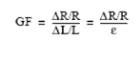
The gauge factor for metallic strain gauges is typically around 2.
3.7.2 Cameras and Video
For video recording of experiments, the lab is equipped with multiple HD quality video cameras. The lab has various Canon cameras for still pictures.
3.7.3. Electronic Instruments
3.7.3.1 Oscilloscopes
The laboratories currently support one 4-channel storage oscilloscope, used mostly for instrumentation calibration and verification of signal integrity. The oscilloscope is a Tektronix model TDS224, and has storage and data acquisition functionality.
3.7.3.2 Digital Multimeters and Voltage Standards
The lab maintains several digital multimeters, all of which are calibrated annually and are used as reference standards for in-house calibrations. Calibration data sheets are available to users who wish to verify quality of measurements.
3.7.4. Instrumentation frames
SEESL is equipped with two instrumentation frames. Two blue frames are located next to the shake tables in the north high bay. These frames are reference frames and are used in specimen instrumentation and can be relocated along the trench as required.

Figure 3.27: Blue instrumentation frame (click to enlarge)
3.7.5 Instrumentation
Most of the in-house built lab equipment is calibrated on need to basis. Instruments used in tests, such as string potentiometers and accelerometers, are calibrated annually and as needed thereafter. Records of all calibrations are kept on file and available upon request.
3.8 Data Acquisition Systems
3.8.1 Pacific Instruments
The 6000 mainframe enclosure from Pacific Instruments has an IEEE-488 interface for control and data output with mounting for 16 analog input and output modules. We have two separate configurations, each of which has 4 enclosures, providing a total of 252 available channels per configuration. These can be separated into individual units with up to 64 channels each to accommodate simultaneous projects.

Figure 3.28: Pacific Instruments 6000 Data Acquisition Mainframe (click to enlarge)
3.8.2 Dell Workstations – Portable DAQ
These systems (3 total) each consist of 16 channels of National Instruments 16 bit data acquisition input channels, 4 analog output channels, and LabVIEW data acquisition development system. The systems are portable and can be used in the SEESL environment as well as in the various teaching labs located throughout CSEE.
3.9 Networks
3.9.1 Description
The lab is equipped with a gigabit local area network (LAN) connected to the campus backbone with a fiber gigabit link. Network ports are located through the lab including ports on the strong floor area, along the shake table trench, and the balcony.
Networking Hardware Configuration:
- 96 1000 Mbps port activations
- 72 100 Mbps port activations
A wireless network covering the entire lab area for both university and non-university personnel. For security reasons, this requires logging in with either a UBIT name account or registering a time-limited guest account. All users using the university's network must agree to and adhere to the University at Buffalo's network policies prior to, and while using, the network.
3.9.2 Multipurpose Workstations
Workstations capable of controlling any data acquisition or control system in the lab. Preloaded with all the necessary software for any system in the lab. Additionally, software to quickly visualize and analyze captured data is preinstalled.
4 Organization
4.1 Laboratory Personnel

Figure 4.1: SEESL Organization Chart (click to enlarge)
4.2 Access Rules
4.2.1 Lab Services
The Structural Engineering and Earthquake Simulation Laboratory (SEESL) at University at Buffalo hosts a series of services for research clients such as planning organizations, for industry and industry partners, for faculty and students at Department of Civil Structural and Environmental Engineering at University at Buffalo, and others. SEESL hosts among other services (i) the CSEE instructional and research testing services on earthquake engineering and structural dynamics; (ii) the research services for other research sponsoring agencies and (iii) the services to industry and other investigative agencies.
All SEESL equipment is available for fees as indicated in the recharge rates page of our website.
4.2.2 Equipment Commitments
The complete safety requirements are listed in the Lab Safety Manual. The following are excerpts from the manual. The requirements listed below are intended to provide a select but incomplete list of do and do nots.
General Requirements:
- Access in the laboratory is permitted when at least one other person is in the laboratory and he or she has been informed of your presence and is in eye or communication contact with you at all times.
- Know where first aid kit, eye wash station, fire exits, fire extinguishers, and electrical disconnects are located.
- Know the location of emergency phones and emergency shut off buttons for the hydraulic system. Use them at the request of lab personnel or in their absence using your best judgment.
- Keep walkways (which are marked with crosshatched yellow tape) clear of all obstacles at all times.
- Do not block fire extinguishers or electrical panels.
- Clean up work area daily.
- If your work will generate dust, cover sensitive equipment before you start, and clean up the dust. Dust cleaning equipment available in the laboratory.
- At the conclusion of testing, safely remove and dispose of the specimens, within the timeframe agreed to in the WORK PLAN. The researcher remains responsible for the removal operations until this task is complete.
Testing Areas:
- When the warning strobe lights are flashing, the hydraulic system is active and testing operations are in progress. Unauthorized personnel must not approach within 10 feet of any hydraulic line, shake table, actuator, or test specimen. Authorization must be obtained from the Technical Services Manager or designated test supervisor
- Authorized personnel, attending a live experiment, must be equipped with a communication device provided by the Technical Services Manager and stay in communication with the test supervisor.
- All other project work may be interrupted, at the direction of the test supervisor, during testing.
- All personnel accessing the basement spaces under the test floor and the service rooms must remain in contact with the test supervisor working above the floor
Cranes, Forklifts, Scissor Lifts:
- Cranes, forklifts, and scissor lifts may not be used unless the operator has been trained and certified by the laboratory Field Safety Officer or designated staff member.
- Operations involving heavy and/or large items requiring the use of the crane and rigging will be performed only by trained laboratory staff members.
- When the crane is used above the hydraulic actuators, controllers, data acquisition systems or hydraulic systems a second staff member must be present as an observer.
- Cranes shall not be left unattended while still attached to a specimen or test fixture.
- Scissor lifts must be operated / attended by a team of two users at times.
Laboratory Equipment:
- The use of power tools is not permitted unless authorized by full time lab personnel.
- Do not move or modify any hydraulic actuators, accumulators, or hydraulic lines. This is only to be done by authorized lab personnel.
- Use of the welder or blow torch is not allowed. These operations are only to be performed by authorized lab personnel.
- All tools must be inspected before use and any defect reported to lab personnel.
- Return tools to the proper location at the end of each working day and when the job is complete.
- Do not use any pre-stressing jacks. This can be done only by authorized lab personnel.
- Ladders must be properly positioned and/or tied off.
Access to Tools:
- The SEESL facility has tools (hand tools, power tools, air tools, and welding tools) that will be made available to personnel who adhere to the requirements noted above and have paid the user fee.
- Power tools can be checked out of the Equipment Room on a daily basis. Hand tools will be available in a kit that can be checked out for the duration of a SEESL project.
- The electric welder and/or cutting torch may be used by qualified professionals who are hired on a subcontract basis to either fabricate or demolish test specimens. In such cases, prior approval from the Operations Manager must be obtained.
- The subcontractor client wishing to use this equipment will be required to verify professional qualifications and prior experience.
- The project PI will be responsible for replacing any lost tools.
- Recharge fees are required for use of tools by personnel using the SEESL lab. The recharge rates are listed in the Recharge Fees. Recharge rates are updated annually.
Access to Instrumentation:
- Instrumentation purchased through SEESL is available for use for a fee. A complete list of instrumentation is identified on the instrumentation part of the website.
- For safety reasons, only SEESL staff are allowed to operate much of the SEESL Laboratory instruments and equipment. Examples include: hydraulic equipment (e.g., pump, manifolds, controllers, actuators and hoses), forklift, scissors lift, electric arc welder, oxygen-acetylene cutting torch, and all computing equipment (except as outlined in the Access to IT Section), cameras (except as outlined below), and associated cabling (except as outlined below). This policy will be enforced strictly. The only exceptions are use of the electric welder and/or cutting torch (as described in the Access to Tools Section), and data sensors and lighting not attached to robotic arms.
- Data sensors (e.g., linear variable differential transformers, string pots, and other reusable sensors not purchased with project funds), lighting equipment and associated cabling may be checked out of the Equipment Room for the period of time identified in the work plan schedule.
- Calibration of this equipment is performed, as needed.
- Video and still image cameras and associated equipment, including robotic arms are to be installed only by SEESL laboratory personnel. SEESL staff will also remove and return all cameras and associated equipment. However, video or still image cameras can be checked out of the Equipment Room on a daily basis during operating hours for short-term use.
Access to the SEESL Controllers:
- For safety reasons, only SEESL staff will be allowed to operate the shake table controllers, the STS controllers, and other equipment controllers, unless otherwise specified
- Non-SEESL staff may be allowed to operate some controller software, if permission is granted and proper training has been provided by SEESL staff.
IT Access:
- The SEESL Laboratory is outfitted with a variety of data acquisition, archiving, and tele-presence equipment, including sensors (e.g., load cells, transducers, and cameras), servers, appliances, and cabling.
- Access to all computers is restricted to SEESL personnel with the exception of the data acquisition computers (if granted permission).
- Accounts on these systems is granted by either the Technical Services Manager or the IT Specialist and are for limited time access. Access can be revoked at any time for any reason.
- All results and metadata for experiments and simulations conducted within the SEESL will be stored. Access can be provided to this data on request and approval for a limited time.
- SEESL staff will not provide curation or data reduction services for a researched funded project.
4.2.3 Safety Rules
Laboratory safety is the highest priority at SEESL. The Department of Civil, Structural and Environmental Engineering (CSEE) has a safety plan that covers the operations of SEESL. This plan requires safety training of all employees, students and visitors. Moreover, it requires periodic inspection of laboratories and other spaces for identification and correction of unsafe conditions. The SEESL Lab Director and Lab Manager are responsible implementing the safety plan and for coordinating the training of employees, students and visitors in the SEESL facility. The SEESL Deputy Direcotr is in charge of development of rules and policies or resolving safety issues in the absence of appropriate policies. The Field Safety Officer, who is a member of the SEESL technical staff, serves as the floor supervisor. The Field Safety Officer is empowered to suspend the work or the visit of any person who does not comply with the safety requirements.
All researchers and users of SEESL must undergo safety training prior to starting work in the laboratory. The training can start with a review of the CSEE Safety Training Manual.
Upon arrival at SEESL, the visitor must take the training class, which includes a walk through of the facilities and a verbal examanation of the rules.
All researchers planning to work in the laboratory must wear personal protection equipment (PPE), which includes:
- Hardhats: mandatory for all who access the testing floor in the laboratory. Hardhats are not required on the third floor observation deck.
- Steel toe shoes or boots: Mandatory in all areas of the testing floors. Safety shoes are not required on the observation deck.
- Gloves: Required whenever assembling or disassembling test specimens or test fixtures.
- Eyeglasses: Mandatory when grinding, impacting, drilling, mixing or hammering.
- Earplugs or earmuffs: Mandatory and available from a member of the SEESL staff when grinding, impacting, or drilling.
- A personal safety harness shall be used when and where required by a member of the SEESL technical staff.
The laboratory will provide hard hats, gloves, eye protection goggles, earplugs and safety harnesses for short term visitors. Safety shoes must be provided by the researcher or user.
4.2.4 Access Fees
4.2.4.1 List of Services
- Two six-degree of freedom earthquake simulators, each with a payload of 50 tons (100 tons combined); for a complete performance description visit our Shake Tables page.
- Three high-performance dynamic actuators (1000 kN capacity, ± 500 mm stroke, 1 m/s velocity, 800 gpm servo-valves), equipped with load cells and displacement transducers.
- Two static actuators (± 2000 kN capacity, ± 500mm stroke), equipped with displacement transducers.
- Data acquisition systems consisting of up to 256 channels.
- A 285m2 (300 sq.ft) strong floor with 610 x 610 mm (2 x 2 ft) tie-down grid.
- A 19.5 x 9 m (60 x 30 ft) strong reaction wall with 610 x 610 mm (2 x 2 ft) tie-down grid.
- A 40 ton crane to move equipment and specimens anywhere within the 900 m2 of the building housing the two shake tables, the strong floor, and the strong reaction wall.
- 50 m2, 9 person capacity collaboration room.
- Accelerometers, displacement transducers and load cells
- A small isolation bearing testing machine with 600 kN vertical load capacity, ± 150 mm stroke and 0.4 m/sec velocity.
- A large isolation bearing testing machine with 7000 kN axial load capacity, ± 125mm stroke and .25 m/sec velocity.
- Ten hydraulic actuators with 10 to 1000 kN load capacity, ± 50 to ± 300mm stroke and maximum velocity of 1.75 m/sec.
- Manifolds, controllers, and all equipment needed for the control of the actuators in item (e) above.
- Multiple portable data acquisition systems, with varying channel capacities
- X-Y recorders, frequency analyzers, portable measuring devices, oscilloscopes, digital multimeters, borescopes, thickness measuring devices, roughness measuring instruments, etc.
- A 30 m3 environmental chamber capable of sustaining temperatures in the range of -40o-C to 50oC.
- A quarter length scale six-story steel model structure with 200 kN weight for use in earthquake- simulator testing.
- A quarter length scale steel bridge model with 150 kN weight and featuring flexible or stiff piers for use in earthquake-simulator testing.
- A versatile, quarter length scale steel model that can be configured in a variety of configurations, including 3-bay, 3-story building and one-bay, 6-story building.
- Welding equipment, hydraulic jacks, forklifts, rigging equipment, etc.
- Heavy hand and machine tools.
- Technical services for assembly of specimens.
- Instrumentation modification and calibration services.
- Parking space provided to non-UB personnel for the duration of their visit.
Note that these facilities and equipment are unique and may not be available due to use on other projects. Careful planning and scheduling is required.
4.2.4.2 Recharge Rates
The use of the SEESL equipment require budgeting according to rates approved by University at Buffalo.
The recharge fees schedule (see below) for all research users is available also from our Recharge Rates page and is updated periodically. All fees are subjected to overhead at current rates of University at Buffalo. The overhead rates change periodically. Before completing any budget, check the referred to page for updated rates.
Resources:
A service agreement prepared before the work can start at SEESL, developed between the SEESL and the client will establish the resources to be utilized in the laboratory work and testing. The agreements will include a detailed description of the fees, and a payment schedule. The agreement will be signed by the authorized representative of the visiting personnel and the SEESL representative.
Agreements:
An agreement will be executed between the visiting personnel and SEESL. The agreement will incorporate by reference all of the rules and requirements. The list below summarizes (but is not limited to) the issues to be addressed by the agreement:
- Work Plan (including the requests for equipment, space, personnel)
- Safety requirements
- Insurance and liability
- Access to facilities
- Resources needed and budget recovery mechanism
- Schedules
The agreement must be signed prior to the start of actual work at SEESL.
4.3 Scheduling
Project Planning / Work Plan:
All researchers planning to access the SEESL site must follow the SEESL guidelines for access to the laboratory's facilities. The following are minimum requirements for such access.
The key element to safe and efficient use of the SEESL equipment, the lab space, and the associated facilities is the project work plan A detailed work plan must be prepared by all users and this plan must be approved in advance of work by the Technical Services Manager. The work plan will be incorporated into the contract between the user and the University at Buffalo on behalf of SEESL.
For University at Buffalo researcher's, during the award process all principal investigators / researchers must submit the work plan indicating the test set-up including fail safe system required, the equipment and instrumentation required, the testing protocol intended, specimen demolition, detailed information concerning the individual work tasks to be performed, the duration of the tasks, the order in which the tasks are to be performed, who will perform the tasks, and the resources required to perform the tasks. A comprehensive schedule with milestones related to the project schedule shall be submitted with the work plan. The plan should address data management and archival needs . The following is an itemized list of issues that must be addressed in the work plan:
- A list of tasks to be performed
- Specimen and fail safe system drawings
- Calculations for the specimen and failsafe system
- An instrumentation plan
- A testing plan
- List of equipment, materials, supplies, tools and personnel to carry out the work tasks
- Space requirements including lab and office space
- A rigging plan including disposal of specimens after testing
- Schedule of tasks including duration and timing
All experiments to be performed using the SEESL equipment should be carefully planned to assure the safety of equipment, operators, and all other users of the laboratory. All researchers should develop detailed plans for the tests set-ups which must include provisions for fail safe of experiment components and equipment. Detailed construction plans for all specimens and test fixtures designed by the visiting researchers must be provided. The plans must include the detailed design of the fail-safe system. Each testing arrangement and specimen must be reviewed and certified (stamped) by a Professional Engineer with experience in dynamic testing (or with demonstrated equivalent qualifications). The SEESL Technical Services Manager will review the completeness of submittal. The Technical Services Manager will work with visiting researchers, review testing plans, and help visiting researchers demonstrate and document that their testing apparatuses satisfy OSHA in full and the State and Campus safety requirements. The Technical Services Manager will be the point of contact for users of SEESL and will provide the information needed to develop a work plan. Please note that the safety of the test set-up and of the SEESL equipment will remain the responsibility of the researcher or user.
The UB researchers will have to negotiate with the SEESL staff a schedule that will be agreed to jointly. For any time in excess of that negotiated with SEESL, fees will be charged. The scheduling for UB researchers will be negotiated with the SEESL Technical Services Manager.
Personnel outside the University at Buffalo will have to negotiate their schedule directly with SEESL Technical Services Manager.
Once activity begins in SEESL, the researcher or user (UB or non-UB) must update the work plan upon any changes and submit them for review and approval by the Technical Services Manager.
Failure to follow policies regarding safety or the work plan may result in the following consequences:
- First offense – verbal reminder
- Second offense – written notification of out of scope work, or safety violation
- Third offense – suspension of work and a mandatory review of both safety and work plan. Research done from outside UB may be terminated directly by SEESL management.
Note: Lab Personnel have the right to stop, or refuse, any task or any operation performed with any equipment used by any lab user.
Schedules:
SEESL is a shared facility which provides services to many entities. SEESL is committed to share all the laboratory equipment and facility up to 50% as required by the Management Operations and Maintenance (MO&M) contract with the University at Buffalo. In order to accommodate all projects, a carefully developed schedule agreement between the researcher and SEESL is required. At the request of the researcher, the Technical Services Manager will develop a schedule which will have to be coordinated with the appropriate personnel. The schedule will be then included in an agreement. The schedule will include all elements requested in the work plan.
Failure to obey the agreed schedule may result in additional fees for the exceeding period. The agreement will include assurances that such fees will be paid to SEESL. In case of major slip in schedule the work may be indefinitely postponed and a new schedule will have to be negotiated jointly with client and the Technical Services Manager.
Business Calendar/Hours
The SEESL laboratory follows the official schedule of the University at Buffalo, including its holiday schedule and unforeseen closures. The laboratory is open 5 days a week between 8:00 am to 4:30 pm. Work after hours or weekends might be possible in special cases with prior approval of the Technical Services Manager. Special safety restrictions and requirements will apply to such work.